TAO EMS

FEATURES

Energy Management System

More than a BMS: A complete Energy Management System

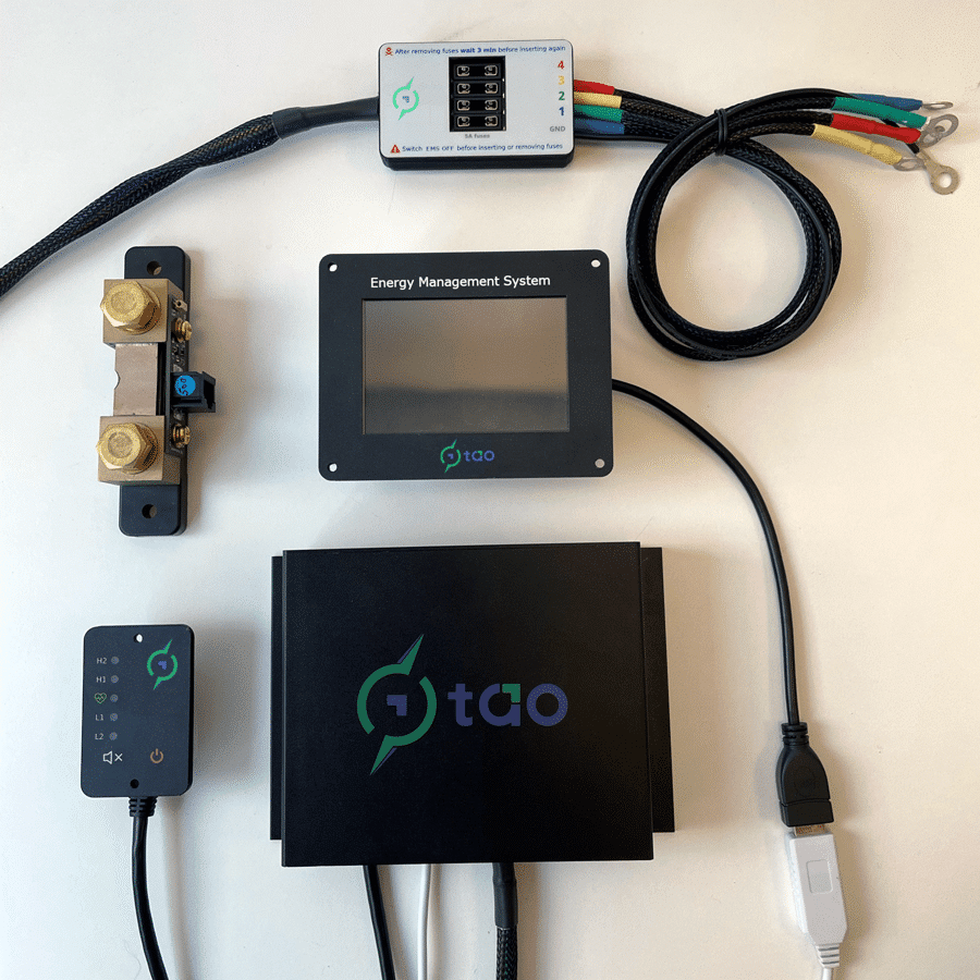
  • protects and manages batteries from 12 to 48 Volt
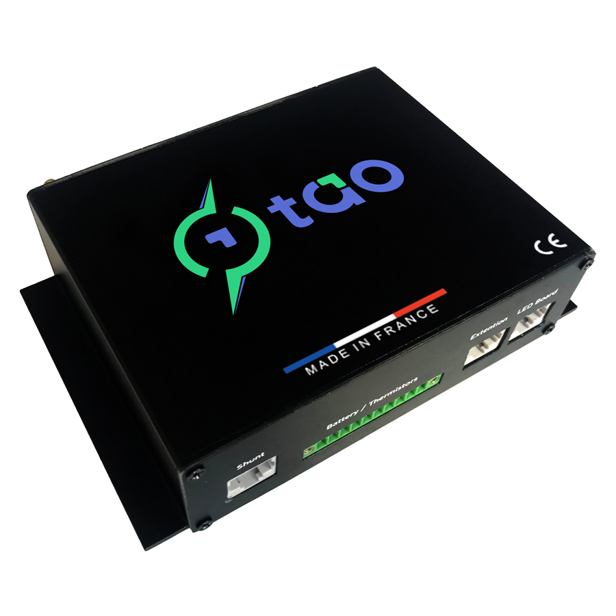
  • simply connect 5 wires per four cells stack and the EMS is operational
  • measures each cell’s voltage and temperature
  • 4 Amp active differential cell balancing based on open cell voltage
  • 20 custom monitoring ranges (voltage, temperature, SOC) to trigger alarms and/or relay outputs
  • 6 NO/NC isolated relay outputs for remote control of external equipment or switching devices
  • charge management to start and stop chargers on your terms
  • integrated pre-charge commands for capacitive loads
  • manages the connection of a backup battery when needed
  • high-precision current measurement for accurate SOC estimation
  • measures cell resistance and actual battery capacity to estimate state of health
  • remote LED and control panel with relay reset and emergency shutdown button
  • continuous self-diagnostics
  • PC and Mac application for configuring the BMS and monitoring the battery
  • fault simulation mode to validate the configuration and indicate that all connected equipment is functioning correctly 

Key Features

Dynamic differential cell balancing
  • keeps cell voltage within a user-defined range at all times

  • activated by a user-defined voltage differential between the cells (either measured voltage or open circuit voltage*)

  • simultaneously discharges the cell with the highest voltage and charges the one with the lowest voltage

  • high efficiency energy transfer with no heat dissipation

  • a total of 4 Amps balancing current
Measurements
  • battery voltage, current*, temperature, and internal resistance*

  • battery state of charge (SOC) *

  • battery state of health (SOH) *

  • measured battery capacity *

  • power consumption

  • number of charge cycles *

  • cell voltage, temperature and resistance
20 custom voltage, temperature and SOC ranges (triggers)
  • Each range is fully programmable:
    • minimum or maximum cell / battery measurements
    • can be based on differential measurements between cells

  • An event is triggered if a measurement falls outside a defined range
    • can activate one or more relay outputs
    • can activate one or more LEDs on the control panel
    • a separate value is used to reset the event (hysteresis)

  • Integrated pre-charge management for capacitive loads
Charge cycle management*
  • the user sets the upper and lower limits for state of charge

  • the chargers are disabled when the upper limit is reached and are enabled when the battery is discharged to the lower limit

  • a full charge is enabled at regular intervals
Remote indicator panel
  • green "heartbeat" LED indicates normal operation and balancing status

  • combination of 4 LEDs for warning and alarm events (red / yellow)

  • 80 Db buzzer with mute button

  • relay outputs reset button

  • emergency shutdown button to activate selected relay outputs
6 relay outputs
  • relay outputs are “dry” contacts (no voltage or polarity)

  • each event trigger, and the emergency shutdown button, can activate zero, one or more relay outputs

  • user-configured wait time between an event trigger and the activation of relay outputs

  • user-configured wait time between relays if two or more relays are activated by a single event

  • each relay output is protected and can withstand 2 Amps continuous (7 Amps for 0.5 second)

  • each relay output can be set as Normally Open (NO) or Normally Closed (NC)

  • compatible with most chargers, converters, and other hardware to control their operation

  • Integrated pre-charge management for capacitive loads
Diagnostics & fault simulation
  • comprehensive self-diagnostics performed at startup and every hour

  • cell voltage and temperature simulation mode for system-wide testing
    • validates ranges and event trigger settings
    • validates relay output configuration and wiring
    • indicates that equipment controlled by the relay outputs is functioning correctly
Factory settings are good to go in most cases
  • 10 preset ranges (triggers):
    • warning level for voltage and temperature (high, low, cell differential)
    • alarm (cutoff) level for voltage and temperature (high, low)

  • 3 preset relay outputs:
    • disconnect charge
    • disconnect load
    • isolate battery

  • the emergency shutdown button activates all the relay outputs sequentially
Previous slide
Next slide
Dynamic differential cell balancing
  • keeps cells voltage within a user defined voltage range at all time

  • activated by a user defined voltage difference between cells (either measured voltage or open circuit voltage*)

  • simultaneously discharges the cell with the highest voltage and charges the cell with the lowest voltage

  • high efficiency energy transfer without any heat dissipation

  • a total of 4 Amps balancing current
Measures
  • battery voltage, current, temperature and internal resistance

  • battery state of charge*

  • battery state of health*

  • battery measured capacity*

  • power consumption

  • number of charge cycles*

  • cell voltage, temperature and resistance
Charge cycle management*
  • each range is fully programmable:
    • minimum or maximum cell / battery measure
    • can be based on differential measure between cells

  • an event is triggered if a measure is outside a defined range
    • can activate one or more relay output
    • can activate one or more led on the control panel
    • a separate value is used to reset the event (hysteresis)

  • Integrated pre-charge management for capacitive loads
Charge cycle management*
  • you set lower and upper limits for state of charge

  • the chargers are disabled when the upper limit is reached and are enabled when the battery is discharged to the lower limit

  • a full charge is enabled at regular intervals
Deported indicator panel
  • green heart beat led for normal operation and balancing status

  • combination of 4 led for warning and alarm events (red / yellow)

  • 8 0dB buzzer with a “silence” push button

  • relay outputs reset button

  • emergency shutdown button to activate selected relay outputs
6 relay outputs
  • relay outputs are “dry” contacts (no voltage / no polarity)

  • each event trigger and the “emergency shutdown” button can activate zero, one or more relay outputs

  • configurable time delay between an event trigger and the activation of relay outputs

  • configurable time delay between relays if more than one relay are activated by one event

  • each relay output is protected and can handle 2 Amps continuous (7 Amps for 0.5 second)

  • each relay output can be set as Normally Open (NO) or Normally Closed (NC)

  • compatible with most equipment to control their operation (chargers, converters….)

  • Integrated pre-charge management for capacitive loads
Diagnostics & fault simulation
  • comprehensive self-diagnostics performed at startup and every hour

  • cell voltage and temperature simulation mode for system wide testing
    • validate ranges and event trigger settings
    • validate relay output configuration and wiring
    • validate proper operation of equipment controlled by the relay outputs
Factory settings are good to go in most cases
  • 10 preset ranges (triggers):
    • warning level for voltage and temperature (high, low, cell differential)
    • alarm (cutoff) level for voltage and temperature (high, low)

  • 3 preset relay outputs:
    • disconnect charge
    • disconnect load
    • isolate battery

  • the emergency shutdown button activates all the relay outputs in a sequential manner
Previous slide
Next slide

* requires the “BMS Shunt”

MORE THAN a BMS...
It is aN “Energy Management System”

TAO EMS (12 volt base)

  • main unit in a 160 x 114 x 46 cm enclosure with:
    • battery wire harness (four cell connectors, a fuse for each cell connection, and a ground)
    • six relay outputs 
    • one connector for the remote indicator and control panel
    • one connector for a current measuring shunt
    • one connector for the computer or the TAO Monitor
  • remote indicator and control panel (with a 10 meter cable)
  • USB cord to connect a PC / Mac
  • application BMS Config to program the BMS, monitor cell status and run diagnostics (Windows 10 / Mac 10.15 and above)

Overview of TAO EMS

Description Value
battery voltage 12 V to 48 V
cell voltage 2.1 V to 4.9 V
number of battery cells in series 4 (up to 16 cells with TAO Extension)
battery cells structure no limit on number of cells in parallel
battery capacity 10 Ah to >10,000 Ah
temperature range -20 °C to +70 °C
cell voltage resolution 0.001 V
cell temperature resolution 1 °C
power consumption 30 mA
computer connection port USB
enclosure size (L x W x H) 160 x 114 x 46 mm
Description Value
output type isolated dry contact (no voltage)
default output state NO or NC (user defined hardware and/or software)
number of outputs 6
maximum stable current per output 2 A
maximum pulse current per output 7 A for 100 ms
output protection internal resettable fuse
Description Value
balance principle dynamic energy transfer between cells
balance start condition adjustable voltage difference between cells
cell voltage compensation for internal resistance yes
balance current 4 A (1.8 A charge + 2.2 A discharge)
energy transfer efficiency > 90 % each way (charge or discharge)
Description Value
current measure principle current shunt with auto ranging amplifier
current range with standard shunt +/- 250 A
use existing shunt yes (mount TAO Shunt PCB on shunt)
current resolution 25 mA
current measure error < 1 %
Description Value
power supply 12 – 24 V
uninterruptible power supply backup rechargeable battery / soft shutdown
screen size 3.5 inch
touchscreen resistive
Translate forum »